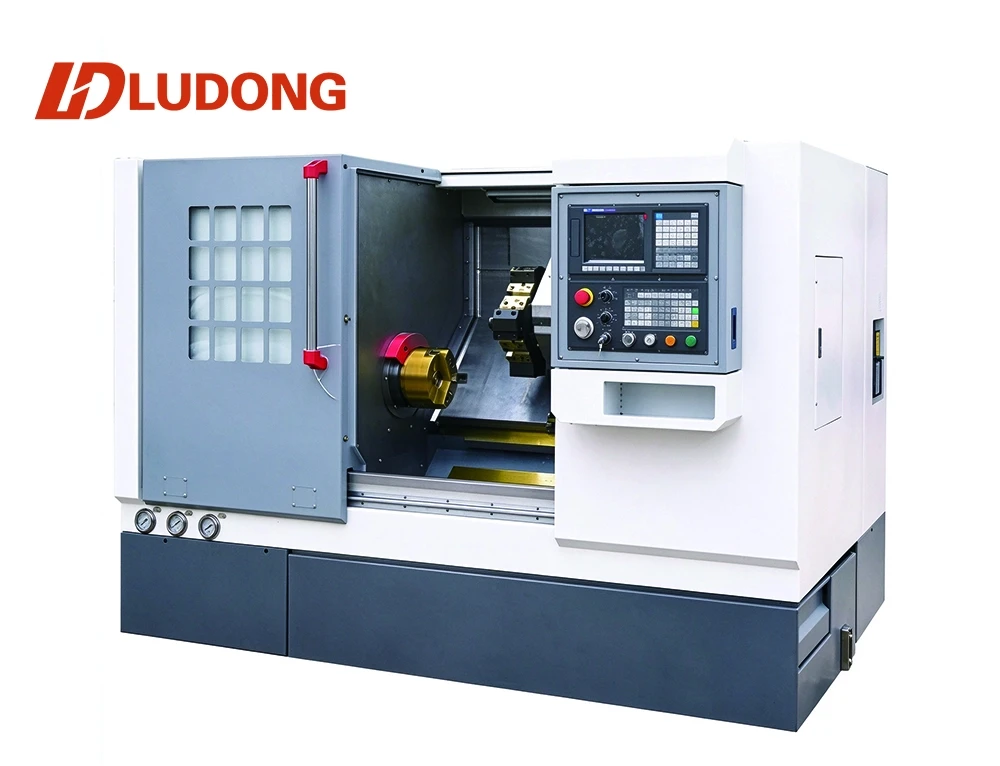

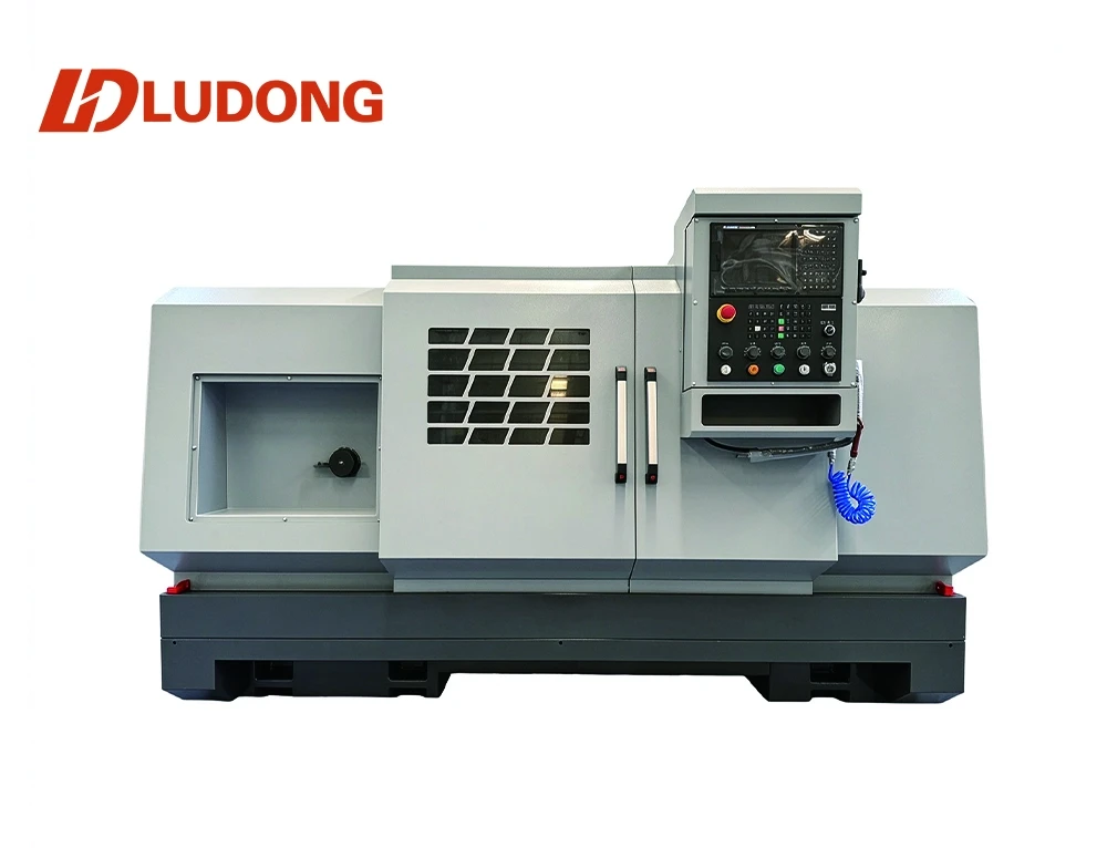
CNC LATHE

LDCK-6166

Machine Features

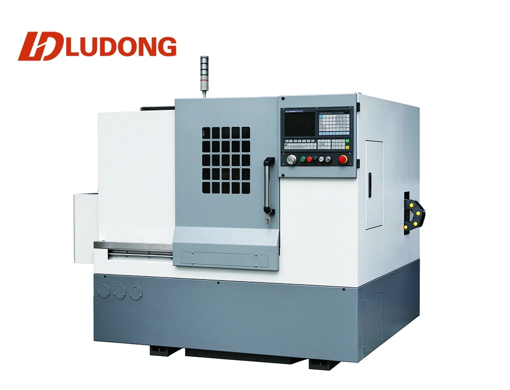
1. The bed adopts an integrated floor-mounted design with densely arranged triangular reinforcing ribs inside for superior stability. It delivers excellent torsional rigidity and long-term precision stability, with a guideway cross-section width of 480 mm.

2. Four spindle box versions (66B / 66C / 66H / 66S) are available to meet diverse machining requirements.

3. The saddle and lower tool carrier are optimally engineered to match the 480 mm wide bed guideway cross-section. The saddle is lengthened to boost torsional rigidity. Additional pressure plates are fitted underneath the saddle to effectively counteract the deflection torque generated during Z-axis travel caused by the extended saddle. This improves the accuracy of Z-axis movement and enhances vibration resistance during interrupted cutting.

4. The tailstock is reinforced for vibration resistance when machining long shafts and heavy load capacity for heavy workpieces. The tailstock body is extended toward the front end where the quill protrudes. This reduces the required quill extension during operation and improves cutting stability.
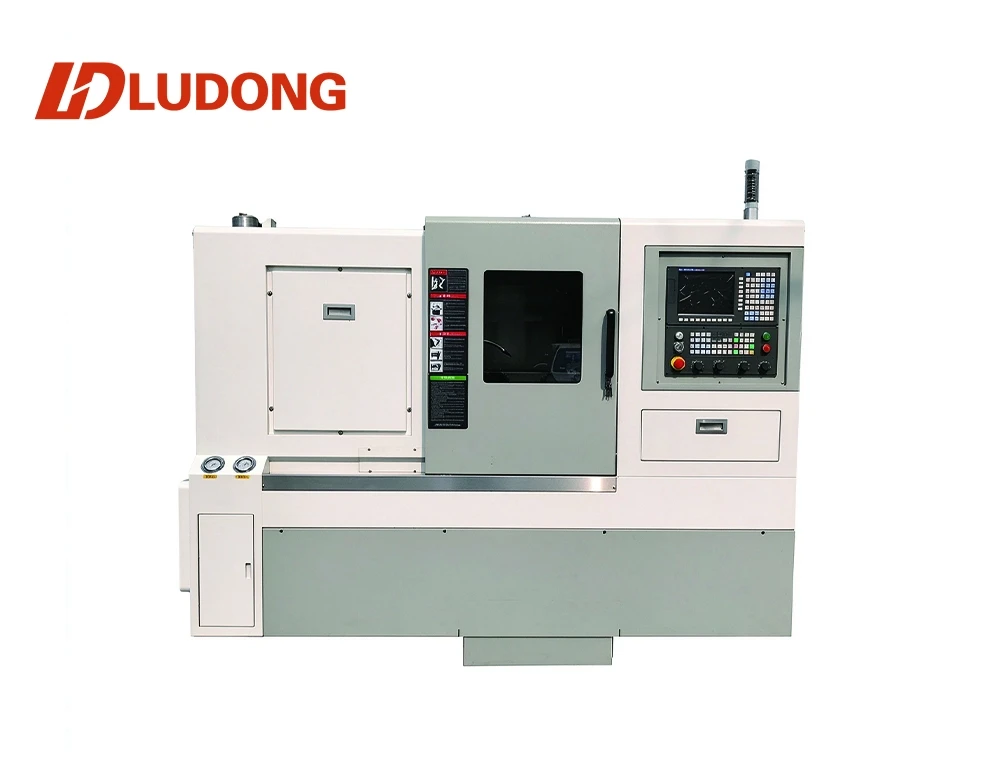
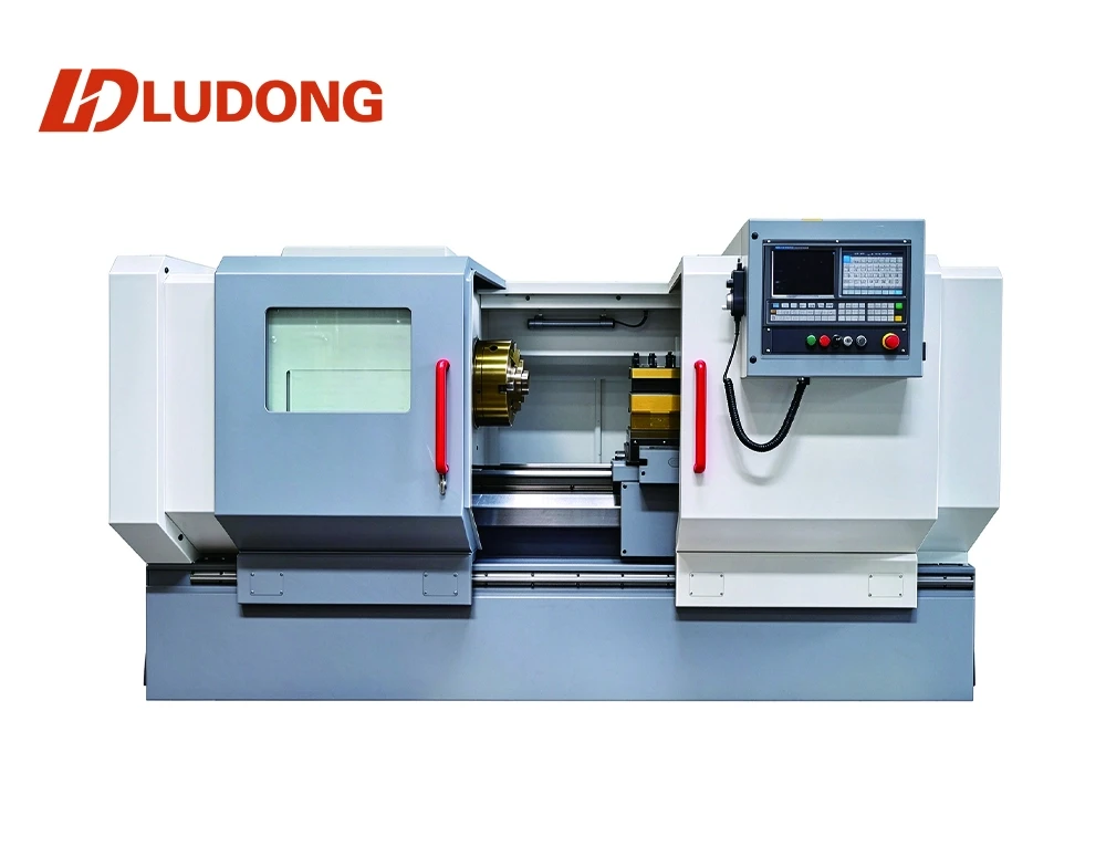
Applications

Tell us the material type, capacity and working conditions. We will recommend a matching model and send a quote.

Product Description

Technical Parameters

Item

Main Specifications

Unit

66B / 66C / 66H / 66S


Bed Working Parameters

Max. Swing over Bed

mm

Φ660

Max. Swing over Cross Slide

mm

①425

Max. X-axis (Cross) Travel

mm

360

Max. Z-axis (Longitudinal) Travel

mm

1200/1700/2200/3200

Max. Distance Between Centers

mm

1100/1600/2100/3100

Bed Guideway Width

mm

480

Lower Tool Slide Width

mm

240


Machining Parameters

Max. Turning Length (Chuck + Tailstock Center)

mm

1000/1500/2000/3000

Max. Turning Dia. on Saddle / For Disc Workpieces

mm

φ630

Max. Turning Dia. on Tool Slide

mm

φ420

Bed Leg

Type


Integrated Floor-mounted Type


Spindle

Spindle Nose Type


A2-8

Spindle Inner Taper


Metric No.90 (1:20)

Spindle Bore Diameter

mm

φ82/105/130/160/205

Spindle Speed (3-speed inverter, stepless within each range) Independent high-speed spindle

rpm

45-260,140-840,550-1600
66H:2000rpm; 66S:3000rpm

Spindle Motor Power

kW

7.5 (11 optional)

Chuck (Manual 3-jaw Chuck)

mm

φ250/320/400


Servo Axes

X-axis / Z-axis Ball Screw (Model)

mm

3206/5010

X-axis / Z-axis Servo Motor Torque

Nm

10/10

Rapid Feed Rate

m/min

6/8


Working Accuracy

Machining Tolerance Grade

level

IT6-IT7

Repeat Positioning Accuracy

mm

X≤0.007; Z≤0.01

Surface Roughness

μm

Ra≤3.2

Tool Shank Size

mm

25×25


Tailstock

Quill Diameter / Travel

mm

Φ80/150

Quill Inner Taper

MT

No.5

General Specifications

Overall Dimension (L × W × H)

mm

2950×1750×1820

Net Weight

kg

3000

Standard reference: GB/T25659.1-2010. The above overall dimensions and weight apply to LDCK6166/1000. See technical agreement for other models.